
Repair: Erres HiFi Sound Project 3537 (Vol. 2)
It's not even a year since his last major repair, which can be found here.
De Erres has had quite a few recordings in the meantime and everything seems to be going well, but there is something I don't like. The right VU meter does not seem to be running properly.
What will look like a simple adjustment turns into a repair of a very small and fragile part!
May 1, 2020

Tools:
- Phillips screwdriver (PH2)
- nippers (small)
- Needle-nose pliers (small)
- Solder + solder tin
- Multimeter
- Adhesive tape
- Magnifying glass (reading lamp)


A small introduction, I have no manual for the Erres 3537, I searched the entire internet but without success. Normally you can adjust a potentiometer on the PCB for the VU meters, but without a manual and without inscription on the PCB itself (which can tell you which potentiometer I have to adjust) I feel far in the dark....
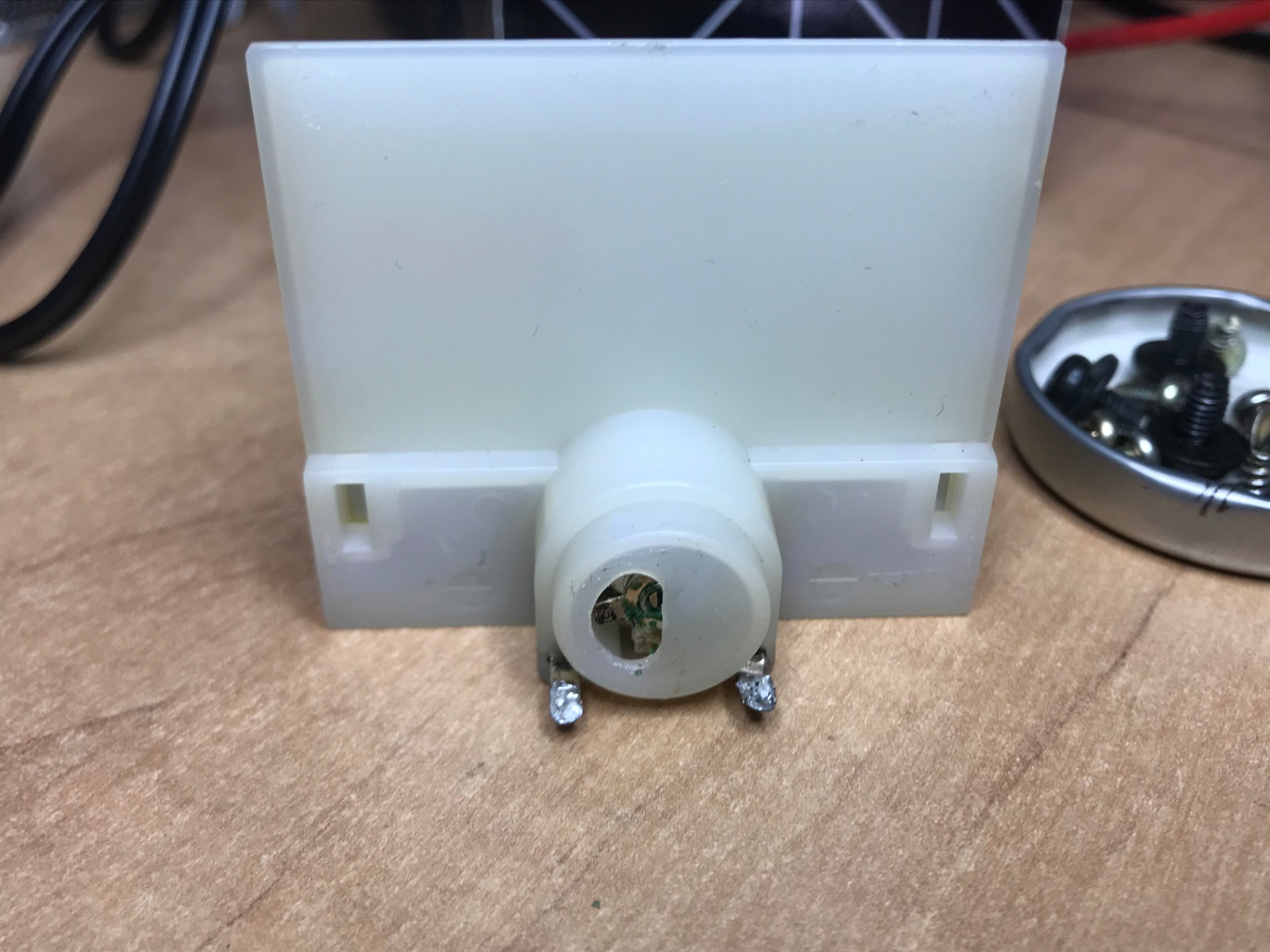
Finally I decided to look whether I could address the deviation on the back of the right VU meter, this was a stupid move resulting in a defective meter.
With a small screwdriver I tried to adjust a screw on the back but it popped out and punctured the fragile interior! Apparently the screw wasn't meant to be turned...

Because I have already described how I disassembled the device, we will skip those steps, for this I use a PH2 Phillips screwdriver.


I grab the multimeter and put it on the measurement mode (I sometimes call this beeping). The value reads 1, for this meter this means that there is an infinitely high resistance, ie there is no connection. So the meter is interrupted somewhere...
If I do the same with the still working meter, I get a varying resistance, this variation is caused by the difference in pitch and volume of the sound. This way I can refer nicely and draw up the above conclusion.


I take the front of the deck off, and partially disassemble the bracket that holds the gauges in place. This way I can get a better look at the faulty meter.


The plastic window is attached with adhesive tape, I remove this so that I also have a better view of the interior. Now I have to be extra careful not to damage the gauge needle...

I search but can't quickly find the cause of the defect, eventually I take the soldering iron and de-solder the wires so that I can take the whole meter out.
The meter works by means of a copper coil that can be seen at the beginning of the needle, the coil is energized by a small round magnet. A variable voltage runs through the coil, the voltage in turn is damped by resistance, which in turn is determined by the volume of the sound. A complex interplay to arrive at a reading...
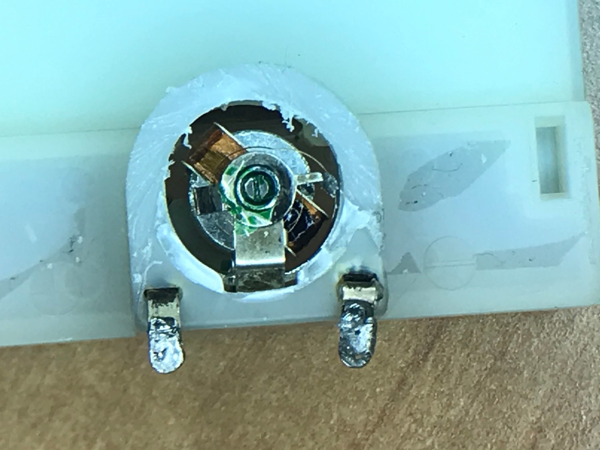
Also on the back of the meter is the same construction, with these two coils the needle can move smoothly and display an accurate value, by measuring at different points I notice that the problem is in the rear coil, logical also because I shot here with the screwdriver. Because the back coil is hidden under the housing of the meter I have to demolish it here, I do this carefully with a wire cutter and a sharp knife.


We're going to go full zoom for a while, to see what I've managed to discover. Because the needle moves continuously and the moving coil has to be supplied with tension, a leaf spring is built in, it springs with the needle, as you can see the connection is broken here.
luckily the spring is still intact, but has come loose at the soldering point on the end. With the cause known, I'll see what solution I can come up with.

Repairing the meter seems like an impossible task if I can believe the internet...
A few days pass, meanwhile I look for the possibility to simply replace the meter, but every time I come up with nothing. If I replace this meter with a new other model, I have to replace the other working meter as well to keep them the same. In the end I conclude that there is no well-fitting meter available. There is no other option than to try and solder the leaf spring back on.....
My only soldering iron has a rather large tip, too big to do this job, besides the connection point of the spring is well hidden under the screw that holds it whole together.
In the end I sacrifice the tip of the soldering iron and make it smaller with a sanding belt.

It is not a beautiful finish, but with this new fine tip it should work...

Because the leaf spring is very small and the soldering iron is large and clumsy, I secure the needle with a rubber band, in this way I ensure that the moving parts remain in the same position during the soldering, because every small movement ensures that the shift the coil and the spring attachment point...

I clamp the smallest screwdriver I have with my helper's hand, so I keep one hand free again. I put the screwdriver in a position that it presses the spring against the mounting point. I can now hold the soldering iron with one hand and the soldering tin with the other.

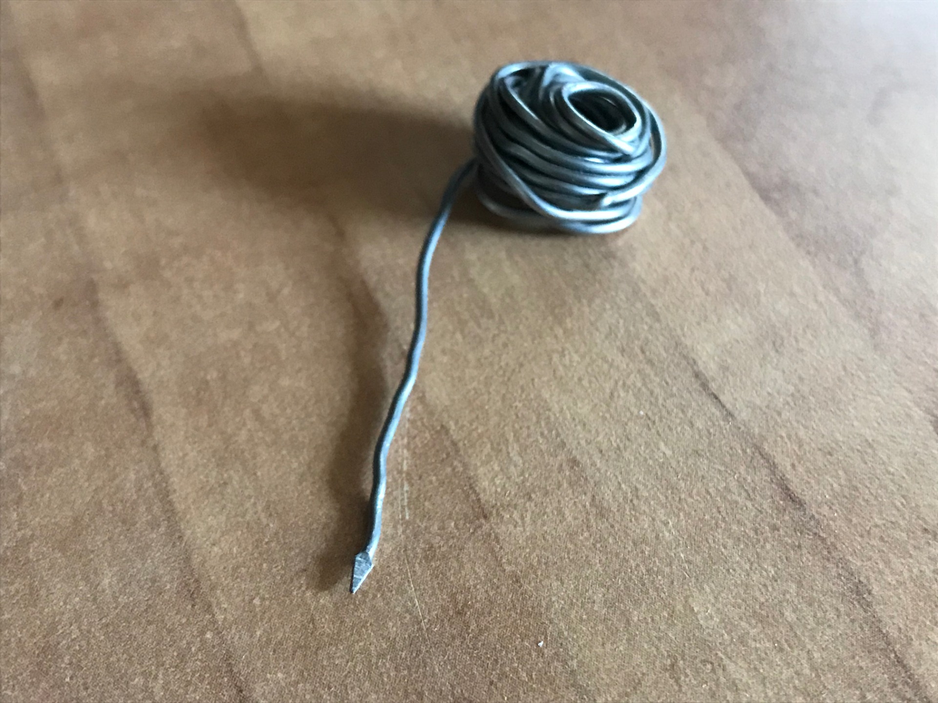
The soldering tin itself is also too thick at 1 millimeter, with a small vice and cutting pliers I work the tin to a small point.

Of course I can't take an action photo of the soldering, so just hold the soldering iron while I take a photo. During the real work I hold the solder against the point to be soldered and tip the bolt against it together with the spring. I have to be careful because the leaf spring is very sensitive to vibration, after 3 hours and several attempts, with my face on the reading lamp peering through the magnifying glass. Will I be able to tighten the spring against the attachment point again, a snail of relief because I had little hope for it from the start and was afraid to damage things further...

I remove the elastic and glue the whole thing shut again. Ironically enough to mention, I have almost all kinds of tools at home but no tape... I borrow these from the neighbor...
The photo above is not quite correct, because the needle is neatly in the rest position while this according to the storyline, shouldn't be the case yet.

I put the meter back in its place and solder the wires again, you now see what I just described above, the needle is not yet correct. The leaf spring needs to be readjusted to return it to its rest position, luckily I still have the other gauge for reference.

Adjusting the meter has to be done manually, for this I use small needle nose pliers. I bend the other attachment point of the leaf spring while looking at the needle on the front. it is a sensitive job with again the risk of damaging the leaf spring.

I connect the deck to a sound source and play a specific frequency (50Hz) that keeps the meters in the same position. This way I check whether the repaired meter is in the correct position.
Make sure that the volume settings are the same for both meters, otherwise you will still have a deviation...
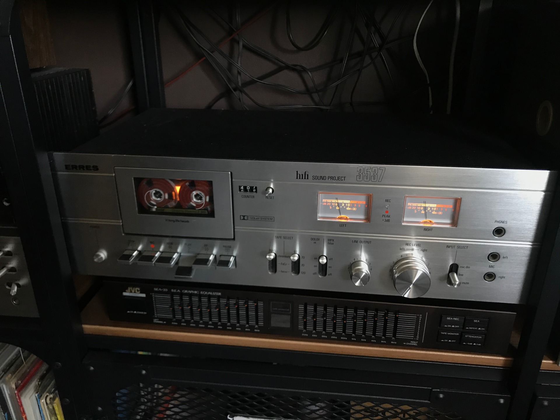

Finally I put in a tape with music and look at the meter, it dances happily to the music again, I'm still amazed that I succeeded!
The meter has been made and adjusted, I can handle it again for the time being. For this deck, however, its end is approaching. I still can't find a manual and can't wait to take it apart again. It is time to refurbish the other decks for general use so that it can go on sale, until then the workhorse will have to go on for a while.
May 27, 2020
Related pages:
Erres 3537 (Vol. 1) Repair
Compact Cassette Information
Marantz SD1000 Cassette Recorder Repair
Compact Cassette Repair
New old tapes! Blog
Compact Cassette Gallery