
Repair: Realistic TR-882
New lights
Older HiFi devices often still work with light bulbs, although their lifespan is still quite long, they all eventually go out. This also applies to LED lights, but the lifespan of these is many times longer. With this repair it is my worry child's turn again. The Realistic TR-882 always has a problem, sometimes big, usually small. Time for a cosmetic procedure today!
July 13, 2019

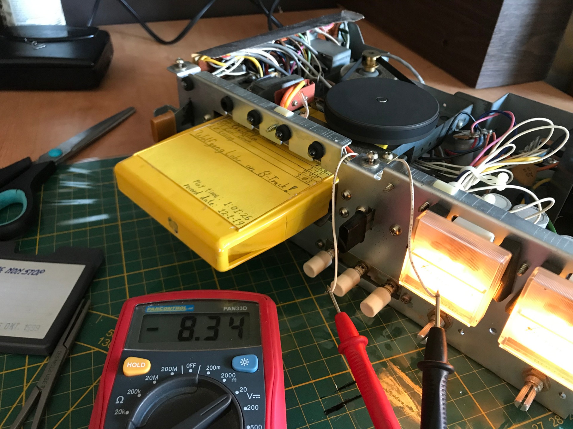
First of all, the following, we are working here with an open housing, and as can be seen in the photo, the voltage is full. If you have insufficient knowledge in electronics, I strongly advise against following my work. If you have sufficient knowledge or even better, are trained in the trade, it is still at your own risk. I am not responsible for the actions you take and cannot guarantee that what I do is the right thing to do. It is also often a challenge for me.
You need the following tools:
- Screwdriver (PH2)
- Vernier Caliper
- Waterpomptang
- pinch
- stripping pliers
- Needle-nose forceps or 'Surgeons' forceps'
- Multimeter (for voltage)
- A helping hand*
- Solder + Tin
- 8-Track cartridge
- Heat Shrink Tubing, LEDs, Resistor

*with a helping hand I mean a bendable figure with crocodile mouth hands and a magnifying glass. I have no idea what you call such a thing so you have to make do with this description. Handy for when you are short of hands or need to keep something stable.
The water pump pliers may not be necessary, but along the way you will see why it is included in my repair.

First I look at what kind of lights are in it, how they are attached and what size they are, in this case slightly less than 5mm diameter. They are in a rubber O-ring, so a small deviation is not so bad.
The vernier caliper is upside down, one of the few tools that I still find difficult to use as a left-hander. Secretly, many things are made for right-handers (logically too). But you only think about it when you notice that a tool does not fit well in the hand.
Well, having lost that, we look at the voltage that the lights need.
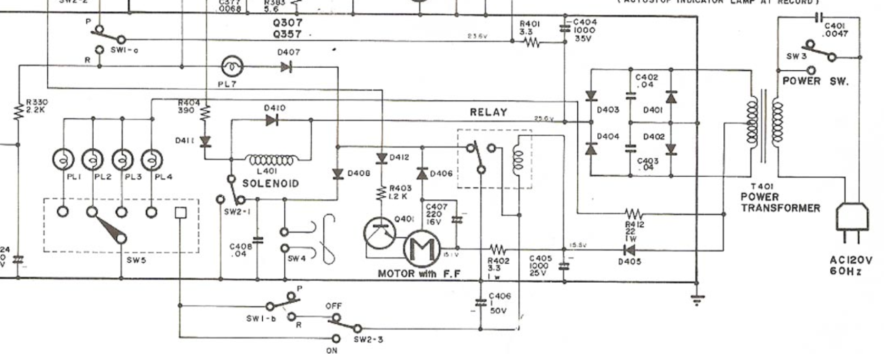
Above is a clipping from the circuit diagram. On the left you see the 5 lights depicted as circles with an IUD in them. On the right the transformer that converts the voltage from 230V AC voltage to the required voltage in DC voltage. It is always useful to be able to consult these types of drawings. This one is clearly old, resistors are still drawn as squiggles and many other circuits shown are drawn very differently these days. Yet many symbols are still very recognizable and their location often reveals what it is all about.
Different voltage. You're more likely to see them from 5, 12 to 24 volts. well, it's a device from the 'roaring' seventies. So we are at peace with it.
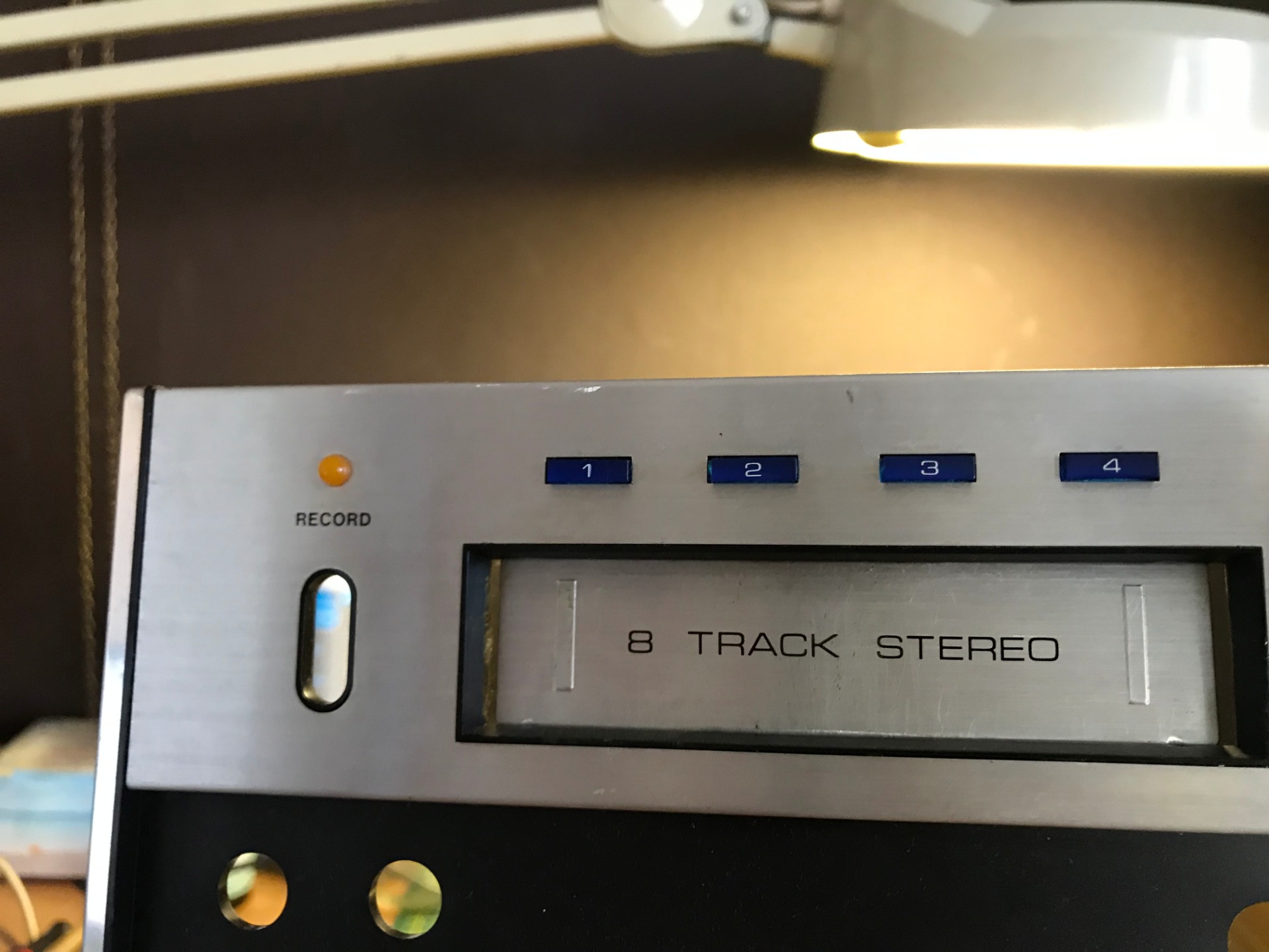
Time to go shopping for new lights, when I look at the front I see that there are colored windows in it. I could go for white lights, but maybe also colored LEDs!

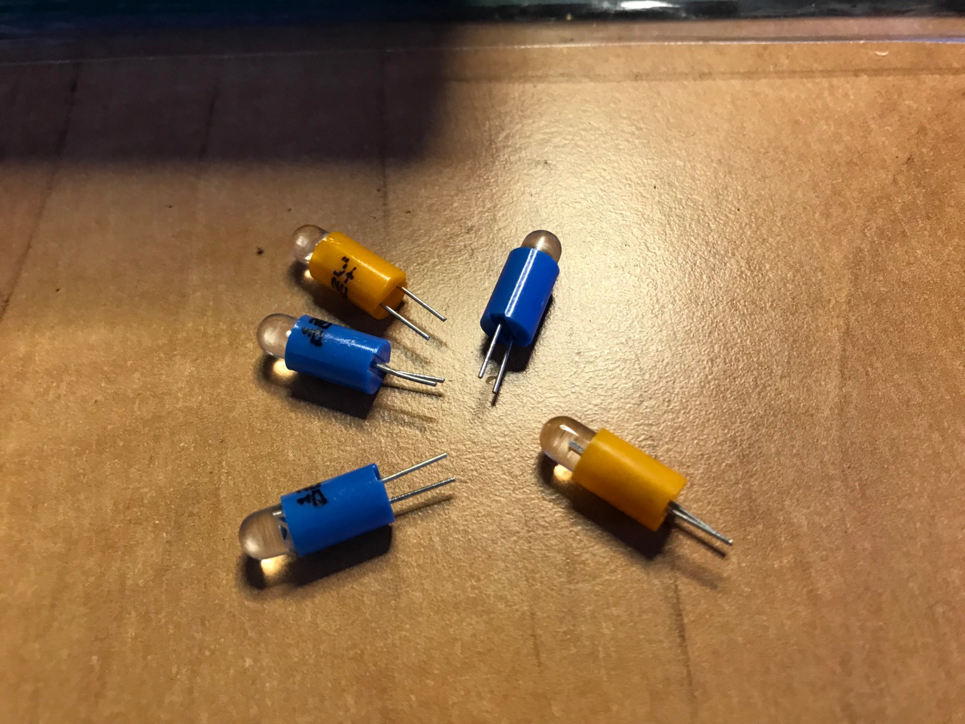
The choice fell on these two candidates. They run on 12VDC, are cheap and fit in the rubber rings (with difficulty). Actually I didn't have many other choices, so I ordered this for a total amount of €16.77 (+shipping), waiting a few days. . . .
Normally small (LED) lights have legs in different lengths, the longest is the plus, the shortest the minus.
But as you can see, they throw that rule overboard here.
So I have to figure out how to connect the lights myself. No problem, the solution will be discussed later.
The LEDs come in aqua-blue and orange-orange. (ofiets)
They match the colors on the front perfectly. Incidentally, they are also blindingly strong, I have experienced this several times.

First of all we pull the plug from the socket, I do this literally every time I have to do something in the machine that doesn't require voltage. I'm not going to indicate it here every time, but you can see for yourself that I had to remove this very often.
A switch as on an extension box is not sufficient protection. I also check every time whether I have pulled the plug, sometimes several times during work. There are parts nearby where the full blow runs through (230VAC). I don't feel like that kind of gossiping.

Well, I strip away the top of the two white wires (+/- 5mm), because the feet of the Leds are of that length. This way I can save on the following:


Heat shrink tubing! 2mm°. I take enough length so that it stays in place better when crimped. Don't forget this step, once you start soldering you can't go back, slide the heat shrink tubing far from where you are going to solder, otherwise it will shrink too early.

The soldering machine switches on and while it slowly comes to temperature, we take a look at how these LEDs should now be placed. The cigar box contains no smoking materials.

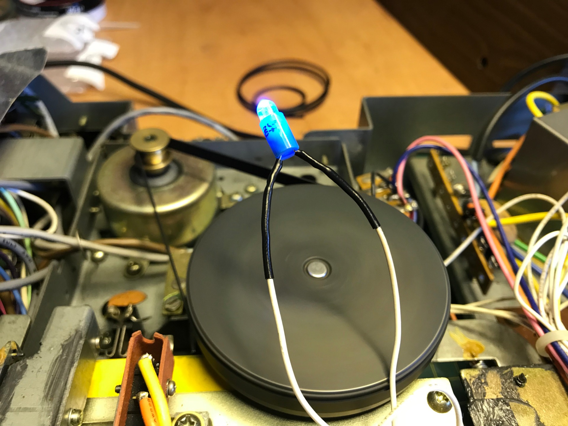
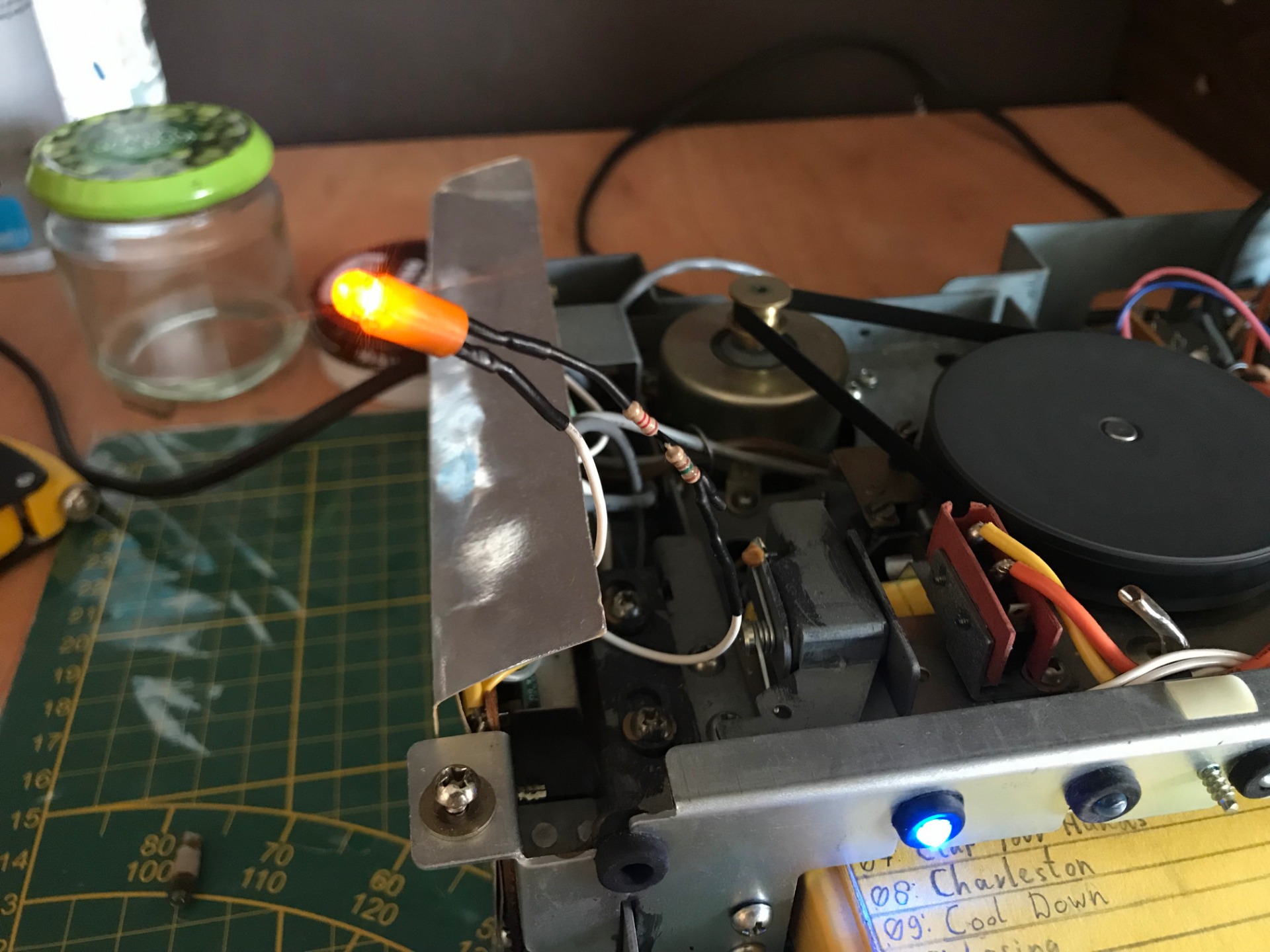
The device is powered, and in this case I select the program in which the light should be on, I hold the LED with the dots against the ends of the wires (be careful not to make a short circuit). He lights up!
Now I know not only that these lights work at this voltage (3.5V difference), but also the direction in which I have to solder them. It is now a matter of remembering how to do them, I mark the plus vein with a pen. There is an inscription on the lamp, which I use here as a reminder. Otherwise I could possibly shorten the leg of the minus, but they are not that long...

My faithful sidekick helps me with holding the ends here. This allows me to work carefully with some tin and the soldering iron.
After soldering, we put the plug back in the socket and see if the light is on, if so. We slide the heat shrink tubing over the exposed piece and heat it with a lighter or the soldering iron until it is tight. The lighter method is not the best here. Do not do this for too long on a small piece and be careful not to break the lamp!

We mount the lamp back in its holder with appropriate force. They are a bit bigger than the old lights. And I don't have enough space to put it back in by hand. The rubber rings are also somewhat dried out after 40+ years. After this I check them again: Plug in, cartridge in. Choose the right program and see if it lights up, unplug and remove the cartridge. If I also switch programs afterwards, the residual energy is still released. (you can read more about this at the end). Normally you have to wait a few minutes for the capacitors to discharge etc. Excuse my impatience.


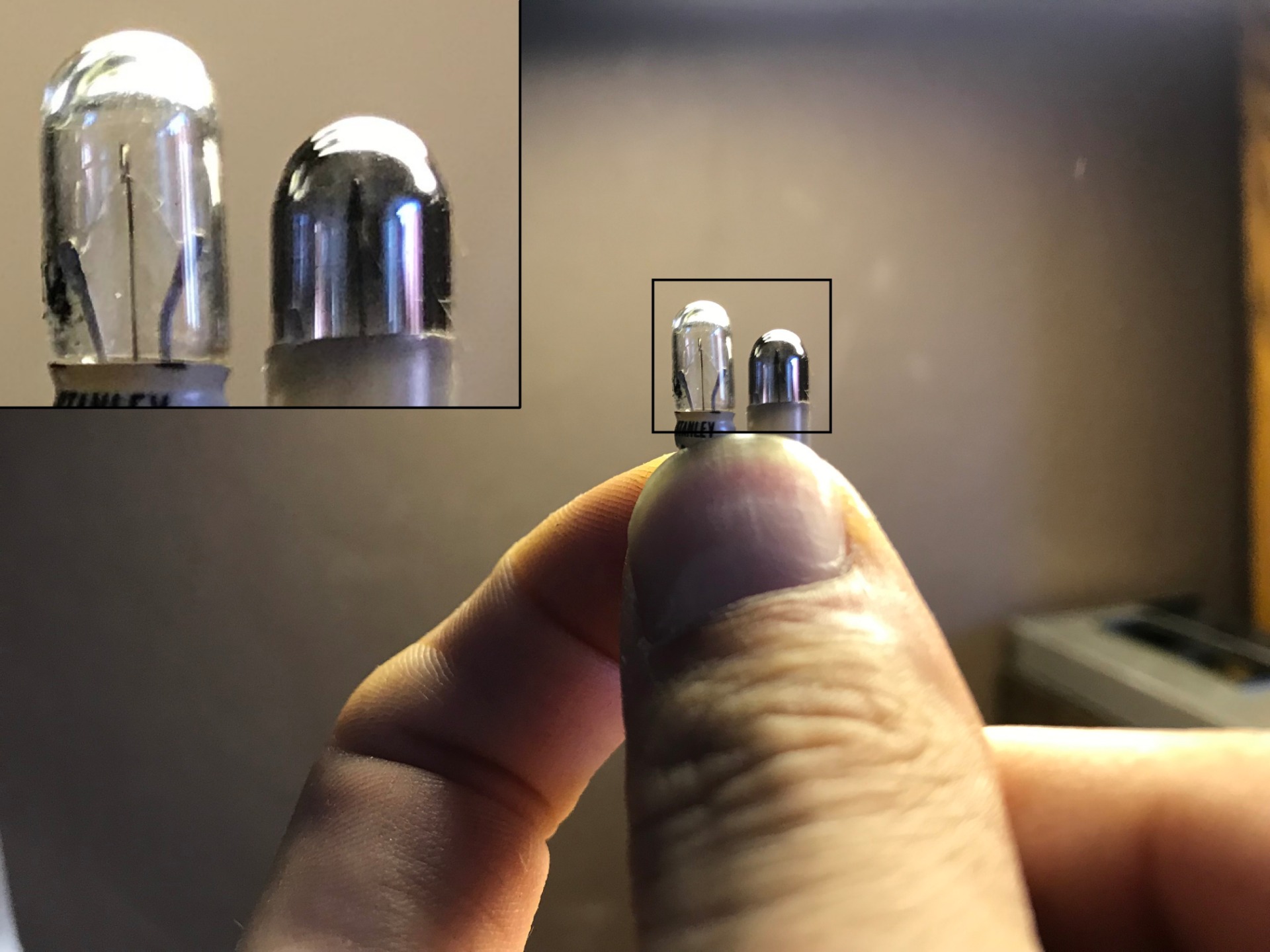
Here's an example with the old one and now it's replaced. A big difference in brightness, the angle of the light is also different, I'm curious about the end result. With this job done, I have four more* to do. My heart sinks for a moment, but I want to get this done now that I have time.
*the fourth is the Recorder lamp, you can see this on the far left, where the orange LED comes in.
Old bulbs out, new bulbs in. I bought a spare of both colors. Maybe I should have kept two of each color in reserve. Should I make a mistake now or should one break in the distant future, I can still replace them.
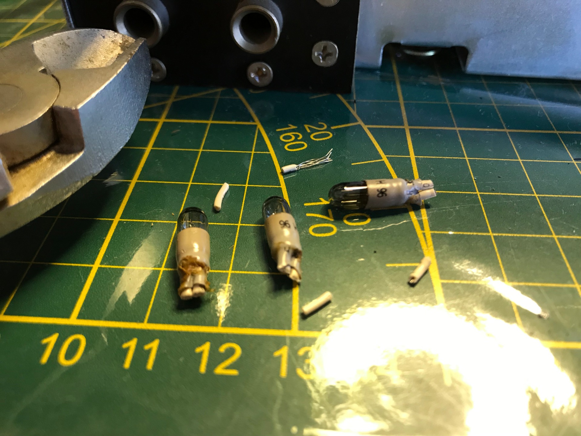
Two of the old light bulbs, to the left of the recorder, to the right of program 1 (which has burned out). Logical actually, program one always comes on first, the recorder lamp is only used for recordings (rarely so). Still they all go out, I want to get this right the first time.


With the surgeon's pliers (we'll call them locking pliers from now on) we take out the last light and cut it off on the edge. I replace them with the new ones, this time do five and have reached my goal.


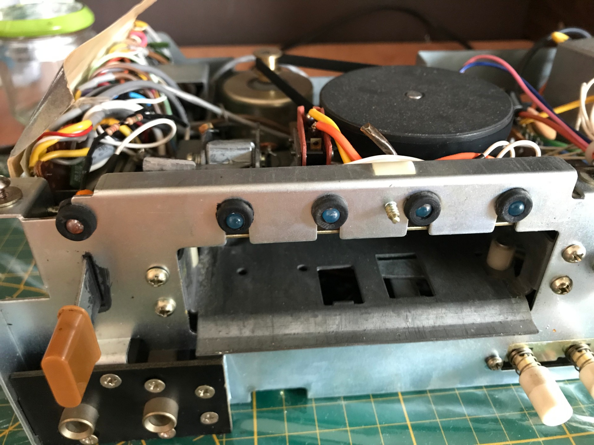
The program lights have now been replaced and the result looks cool, now just the record light and we're done! In the meantime, things are moving at a good pace, with each light it gets easier.

Before I replace the rocord light, I first check what voltage is coming from these two wires, because they are soldered somewhere else on a printed circuit board.
Here we measure a good 16V.
Another strange voltage, moreover the lights only go up to 12V and the difference is now a bit too big. . . .
. . . Anyway, let's see how this one does.
There we have the same photo as seen in the beginning, it burns perfectly. I watch for a while to see if it takes on a deeper color or goes towards red, it's starting to get very warm now, so I take it off again. The solution here is a resistor.
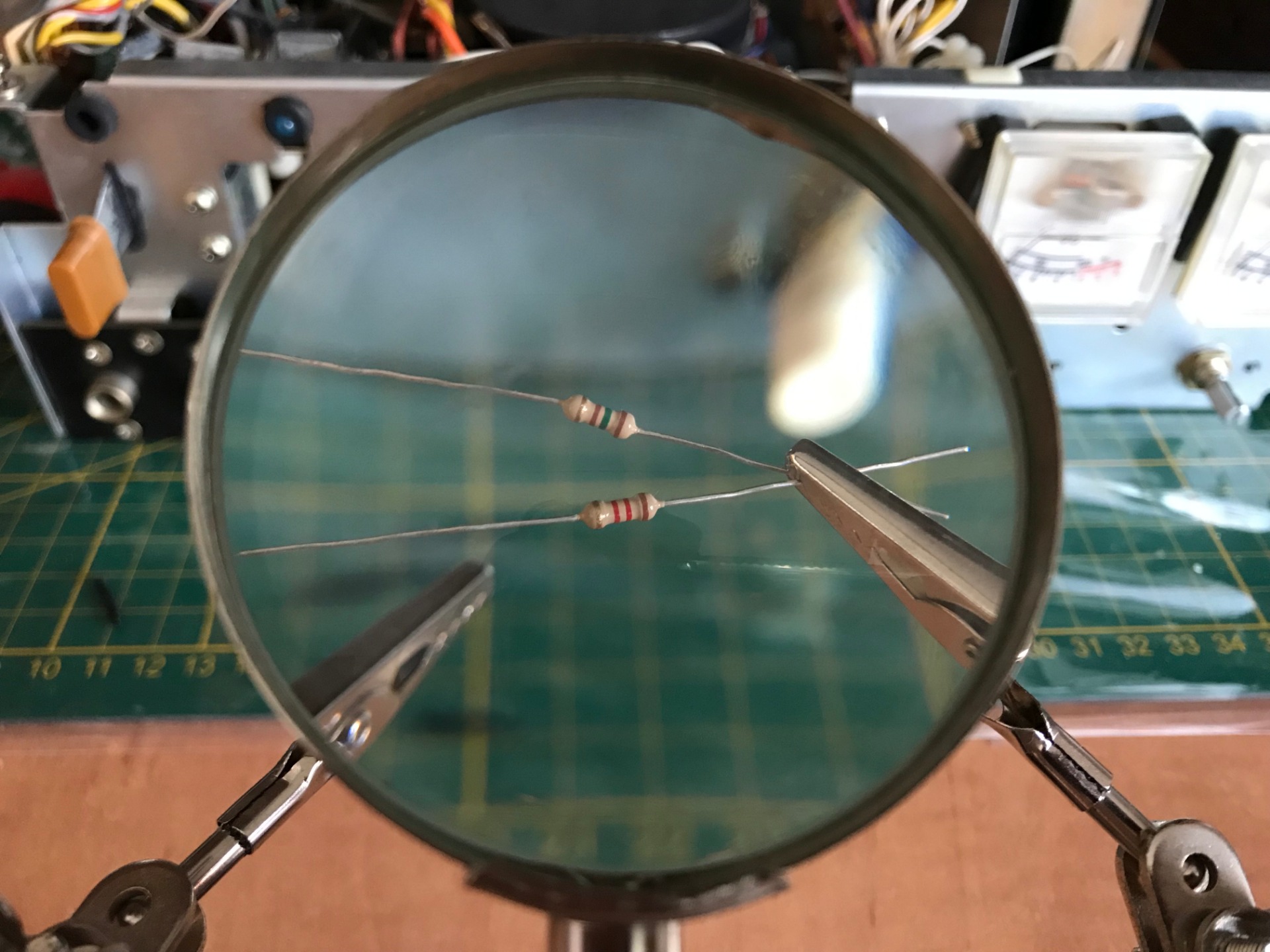
Resistances seen through the magnifying glass of my helping hand. The colored rings you see on resistors can be added up as a sum. Each ring has a specific value in Ω (Ohms), added together these rings tell the total resistance value. If you calculate them, you arrive at the value I need, but I won't reveal it. Calculate that yourself.
Before you start using resistors, it is advised to measure them. Resistors work in both directions, so there is no real plus and minus.
Just a jump forward, the light is on and works perfectly. You now see resistors in between together with a load of heat shrink tubing. I've left it on for a while to make sure it continues to work. Assembling this light was easier than the others.
Now that the machine is open in front of us, it can't hurt to give it some extra love,
after all, it is the worry child, so everything I do extra now can only improve the quality and appearance.


The mechanical parts are smeared with a black paste, which is now more than 40 years old. I cleaned it (as far as I could) and provided it with new grease. The sound you now hear when shifting these components is noticeably softer and smoother. I do the same with every other part where I see this paste.


It is now also easy to clean the various contact points with a cotton swab.
The Program Head detects an aluminum strip on the tape and switches the program when it makes contact. The Capstan presses the tape against the Pinch Roller (a rubber roller). This is how he pulls the tape forward.
Of course the most important, the erase/write/read head.
I clean the heads with 96% Alcohol (also called Ketonatus).

So nice that you can jump from one photo to another. Still, it took me an hour to clean everything and put it back together.
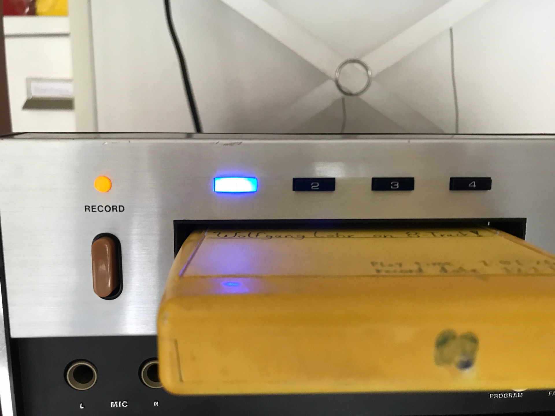

Here's the end result! Although it looks very bright on camera, it looks fantastic in real life! A deep blue color is now coming from the program display and the record light is a bit dim but that's okay. It looks even more beautiful in the dark!

Although the lights now scream LED, I have kept the VU meters original, I don't know how long they will last, but I think the light bulbs give them a much nicer look than the strong LED light.

For the final shot, the Realistic TR-882 in its newfound glory, on top of a JVC Graphic Equalizer (SEA-33). Although many HiFi enthusiasts dislike physically adjusting your music (by, for example, a Graphic Equalizer). This thing comes into its own with this 8-Track recorder. If you click on the photo, you will see that the adjustment is minimal and only dampens the low tones.
In his first round of play you can clearly hear improvement, he makes less noise and when he switches programs you are shocked, you no longer have the problem. Still I notice that the stereo sometimes doesn't come through properly and there is some Wow and Flutter in it. But this turns out to be the Cartridge.
I've repaired it several times, replaced its belt, and previously re-adjusted it because it sometimes skipped a program. Now that the lights have been replaced and everything is lubricated again, he should be able to handle it again for the time being.

The Cartridge you've seen throughout the story is a self-recorded 8-Track by Wolfgang Lohr. The recording date and playlist are no longer original, I recorded it for the first time on May 04, 2017, but provided it with new tape in early 2019. The player had eaten it. You can read more about 8-Track repairs at the bottom of the page. Wolfgang Lohr's music can be found here on Youtube.
July 26, 2019
Related pages:
- Realistic TR-882 Vol. 2 (adjust and test)
- 8-Track Cartridge Repair
- 8-Track Information
- 8-Track Gallery