
Repair: Pioneer JT-215A
I've always been a little crazy about mechanical timepieces, if you can get hold of these in a 'flip clock' version and combine it with your HiFi equipment, the picture is complete. It comes with some problems, the movement would not work, one of the buttons is missing and another one would be stuck. There are also holes drilled on the top of the hood. But partly because of this I was able to buy it reasonably (they are not cheap) and the rarity factor makes it a difficult device to come by. Still, it's here now, so let's take a quick look.
August 8, 2019
We are going to work again on a device that works on mains voltage. I have to take measurements when the voltage is on and the many open parts together with the metal housing don't make it any easier. The mechanics are also fragile and it is not easy to get replacement parts. Work carefully and only if you have sufficient knowledge. I am not responsible for anything, follow the steps at your own risk!
Tools and Resources:
- Screwdriver (PH2)
- Small needle nose pliers or the right Seegerring pliers
- Small locking pliers
- Tray for screws
- European plugs (male and female)
- Multimeter
- (ball bearing) grease + cotton swabs
- Mild cleaning agents + cloth

During the repair I have to replace parts, the new parts are made with heavy machines, these are not included in the tool list.
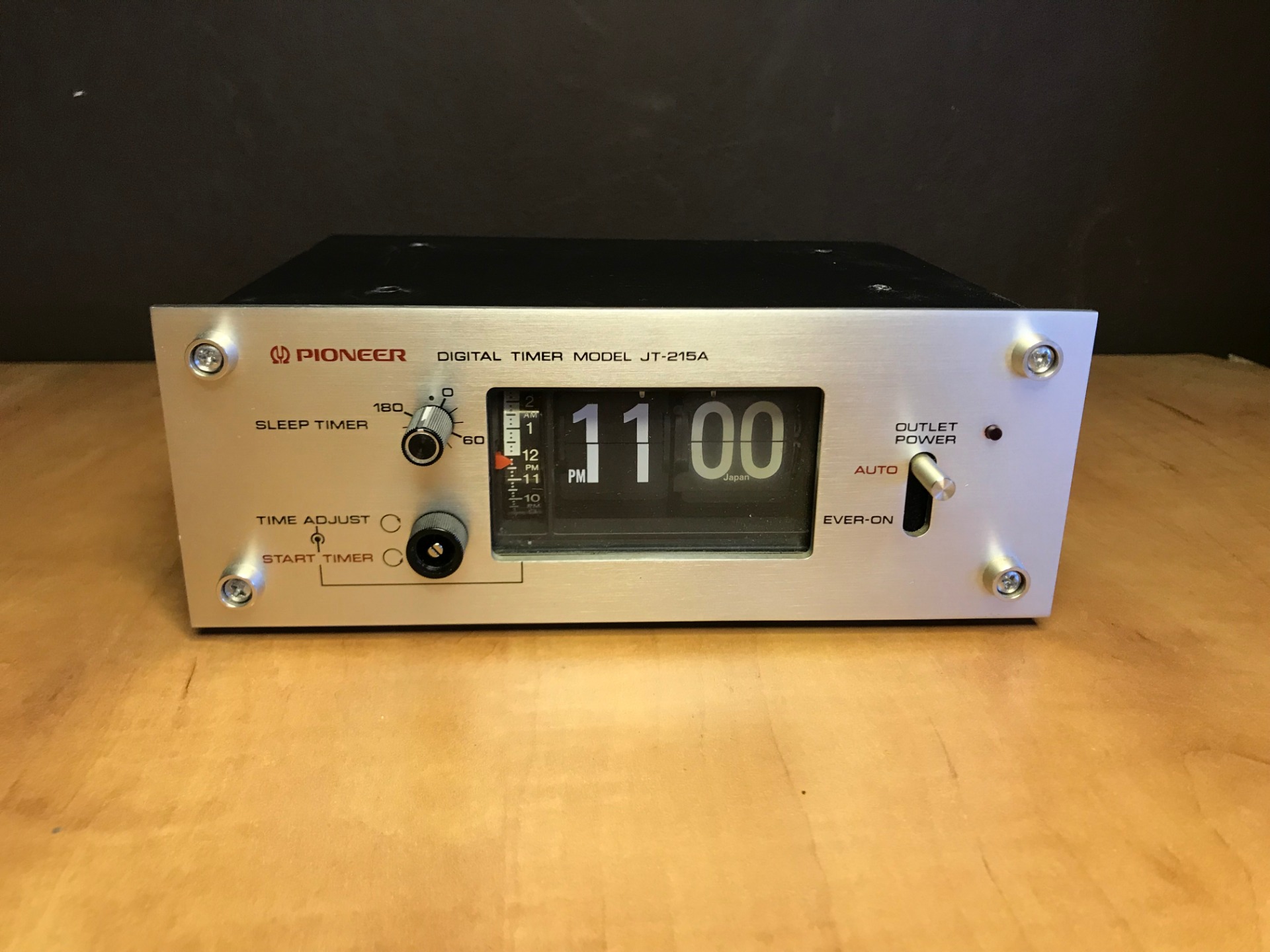
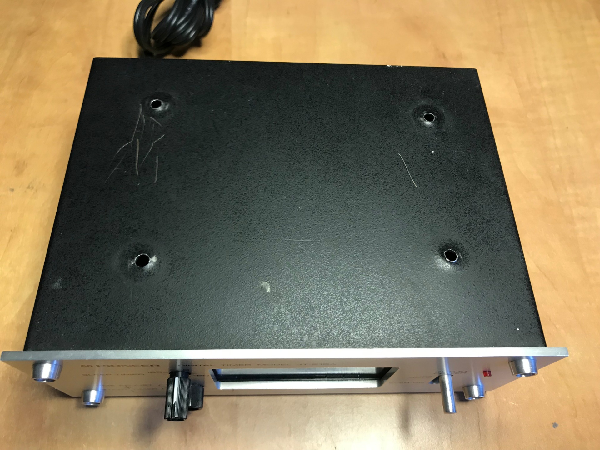
As you can see there are holes in the top of the machine, although this isn't an immediate problem it looks sloppy, I'll address this later. For now we focus on what is required. For example, a rotary switch (potentiometer) is missing, which you use to set the alarm (so that it switches on at the selected time). There is also an American cord at the back and the voltage is set to 120VAC (American mains voltage).


We start by setting the voltage and replace the plug for a European model.

Adjusting the input voltage is not difficult, with a large flat screwdriver we remove the fuse and then also remove the plug for incoming voltage. I blew the fuse and it's still good. Inscription says 1 Ampere. I put the plug on 220V, this is the old Dutch mains voltage, nowadays this is 230V but this does not cause any problems, many older devices (in Europe) still work on 220V.


I cut the cord (which is of course not under tension) halfway through, I will need it later together with the American plug. I get a European one at the local parts store.
Mounting the new plug on the device is not much, because this is alternating voltage, it does not matter which wire is on which pin. There is no grounding, so you can hardly go wrong. Connect, reassemble and that's it Kees (no, that's not my name).
On the bottom of the device is a switch for the frequency in Hertz, in Europe the mains voltage is supplied with 50Hz. This is where I put the switch.


The first time is always 'exciting', it starts normally or everything ends here with a big bang. Fortunately, the latter does not happen. I see a faint light burning under the timepiece (a neon light like you find in power strips). A red light is lit on the right as an indicator that it is sending its voltage to the output (this means that devices that are connected are also on).
We check all buttons. Although the seller said that one of the rotary knobs would be stuck, that is not the case with me. I can still operate the missing button with the small needle nose pliers. Time to measure things up.
For now I set the clock to the current time and watch, meanwhile I listen for a tick and check to see if the gears inside move. No action to be seen...

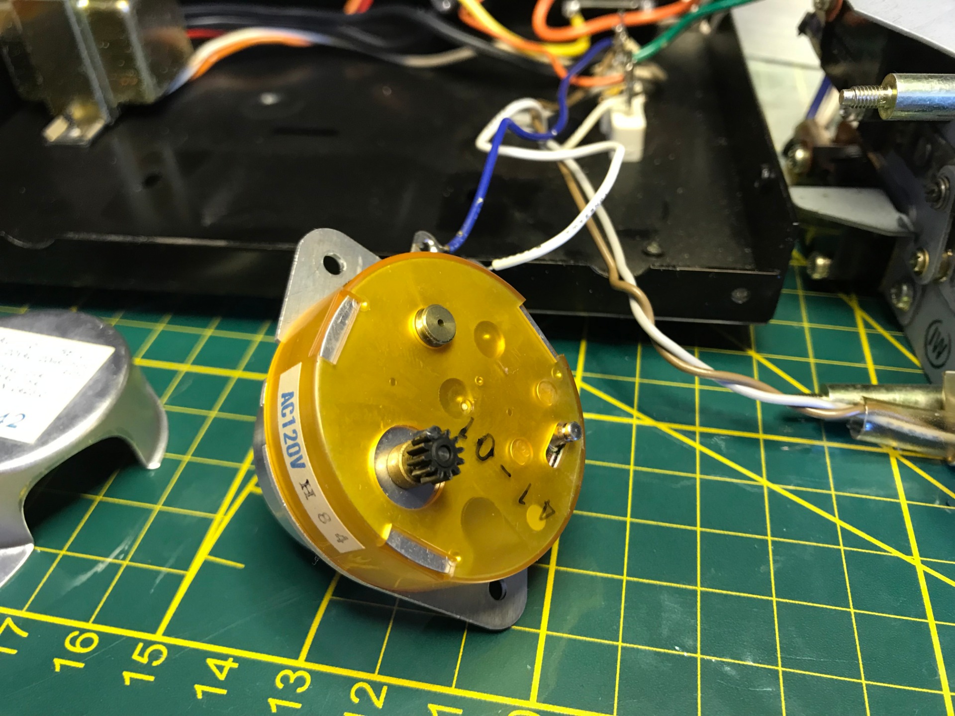
Yes, that's right, a tangle of wires, luckily most of them are colored, which makes searching easier. The motor of the clockwork and the neon light both work on 120VAC, a small converter converts the incoming voltage directly. The indicator light has a resistance so it works at an even lower voltage.


The measurements show what I would expect. This indicates that the motor is receiving voltage.
Small point of attention. I staged the measurements you see here. I did the measurements beforehand and set the multimeter to Hold, so there is no voltage on the device in the photos, taking pictures with one hand and measuring with the other is a bit too dangerous for me... On the other hand, I'm still wrong busy, jewelry... Apologies for my inappropriate action.
No seriously, don't keep jewelry on while doing this. If your ring were to slip off your finger or your watch could come off, things could go wrong.
In the meantime I search the internet for a manual but it is nowhere to be found, it is often asked by others but without success.
Here and there I also read from others about defects: clocks that have jammed, engines that are 'fried' and many other problems.

We go one level up and take the whole device apart, the wires are short so can't separate them far from each other. This way I can possibly rule out where the problem is, I'll start with the engine.

Here we see the switch for the frequency to be chosen (Hertz), it is fixed with a Seegerring I don't have any tools for that so use needle-nose pliers to loosen it, of course it shoots away and disappears under my desk... and I find him happy again. My idea was to remove the plastic housing but decide to look at it that way first. I check again that there is no contact and put the power back on.
First I watch carefully to see if I see anything moving, I soon realize that the transmission to the gear is built in such a way that the movement is minimal, too small to see with the eye. Listening to taps or the like also yields nothing, the movement of the motor is too fine for this.
When I put my finger on the plastic housing I feel a vibration, this is good news but does not give a definitive answer yet. Another technique is to hold a screwdriver against it and hold the end to the ear, this way I hear the buzz.
I also feel that the engine has become warm (not yet hot), again indications but no certainty of correct operation.
Now that the motor has been disconnected, I check whether the movement itself can now move freely (it is not stuck or running rough). It does indeed run smoothly, fortunately this is not the problem.
To see if the motor is running I put a small dab of grease on the gear, take a picture of the current position and put voltage on it. Time may provide clarity about the condition of the engine.
If it works correctly, the gear should have shifted in a few minutes. Which can be read from the position of the dot of fat. If it's short-circuited or gets too hot, then I can throw it away.
On the internet I sniff for a possible replacement engine, it is a separate copy and I have no hits on the internet. I keep looking for parts for the timer itself, but nothing at all. So we hope that the motor works or can be repaired...
I check the temperature again later, the motor has warmed up a bit but I don't think it is 'too' hot, which is difficult to say.
In the meantime I will continue with the previously cut cord. Because the two outputs of the timer are also American, I now use the old cord as an adapter.
I put a European contact at the other end so that I can easily connect my devices to it later.
For now I have one American cord, if I have a second one later, I can also use the second output of the timer.


I strip away the ends of the cord and tin them, then I take the plug apart. I have to say that the white housing smells really bad! It is of course the novelty of the plastic, a dirty chemical smell is attached to it.

the connection is again not difficult, the wires go to the terminals on the outside, in the middle is the grounding, but we don't have it.
If you click on the picture you will see that I connect the wires on the left side of the clamp. You tighten the screws in a clockwise direction. This way the wires cannot come loose when tightened.
Still I make a typical beginner's mistake, the jacket of the plug is not on the cable yet, so I have to disconnect it and reconnect it...
In the meantime, enough time has passed to see if the motor works. I check the gear position and see that it has not shifted, the motor is probably broken or stuck. In the latter case, there is a chance that I have just fried it...
Since it vibrates and gets hot, I suspect something of a jam in the gear mechanism that is hidden under the plastic housing. Time to open it up, of course I'll take the tension off first!

Oops... Unfortunately I had few options, the plastic hood was clicked in such a way that I couldn't get it off from the outside, the only option was to break off a few pieces and push the hood open from the inside. This only worked because the plastic has become so stiff (after all, it is also 40 years old). Broke off more than I hoped. Still, it is still usable and maybe I can make something beautiful out of it if I put it back together.

Now with the hood removed we have a clear view of the interior, the first thing that strikes me is that the sprocket below the black one is damaged (circled in red), there is a crack in it. Because of this you have a chance that this last white gear does not transfer its movement well to the shaft itself, as a result the black gear may not rotate.
I also noticed that if I turn the metal cap at the bottom I can turn the entire gear. during testing I did not see it turning either, the metal cap has holes at the bottom, I suspect that this cap provides ventilation while turning and is therefore directly connected to the central shaft. So I have the following two suspicions.
The last transmission probably won't work due to the broken hub of the sprocket.
I did not see the metal cover rotate during testing, suspect the motor is broken or stuck
The problem of the transmission I can easily solve, if I move the black sprocket back and forth I see the white one below move with no play, I can't turn the black too far because the rest of the transmission is too heavy for that. This is a good sign, the hub is still transmitting motion to the axle. of course everything now runs without the load of the heavy timepiece itself, if I can apply some superglue to this and keep the break closed with pliers I can probably fix this.
That the motor does not move is more worrying, there is no replacement and a defective motor is difficult to repair, I still hope it is a simple defect but fear worse.
During testing I noticed that there was vibration and heat development, the motor might still work but could be stuck, I will have to examine the motor carefully to see what could be wrong with it.

I then asked a colleague of mine for advice, who told me that the engine can have problems with its start-up (literally starting to move from a standstill), after all, this is the heaviest moment for the engine. Once it gets going, it may well work. I couldn't fault this in the previous test, but decided to try it again, and yes! I give the engine a little helping hand and it gets going! So it still works, just has trouble getting started.
After some extra research about the type of motor I find out that it contains permanent magnets. But don't let that fool you, no magnet is truly permanent.
influences such as heat, peak currents and age can affect these magnets and weaken them, I had already noticed that the device has often been too hot (there were light soot spots on the housing). So there is a good chance that these magnets are weakened by heat, so that the motor can no longer get over its start. The previous owner probably had it on for years.

For now I repair the break in the hub with superglue, a very small dot of glue is sufficient, pinching with needle-nose pliers is not possible, it will probably stick to the hub. I lubricate the gears with a little grease and drip some fine oil on the central shaft of the motor.
I set up a setup where my assistant holds the engine and I let it run for an hour or two, in this way the grease and oil can be well spread. I have noticed that once it gets going, the engine easily gets up to speed again after a short stop. But if it has stood still for a while, it is necessary to start it up again.

At work we have a cool device to measure rotational speeds, in this setup I use the laser function and stick a piece of reflective tape on the motor. The RPM is shown as the magic number 333.3 RPM. It is not the most accurate method to measure this, but it is a good guideline, it also runs stable, the speed does not change during the measurement.
Again and again I test the engine, I turn it on, crank it up, set the time correctly and let it run for several hours. With every check I do, it runs right up to the minute with real time. So the engine isn't that bad.
In the meantime I am already a month further and still have plenty to do with the housing. I'll leave the problem of the engine for what it is and go to the other points.


The hood is pierced and full of scratches, I can make a brand new hood but I spend too much time for that, I decide to reuse it. Sand off the old paint, I flatten the dents around the holes again. Finally, I grind a large square hole on top of the hood. The device gets way too hot and has no ventilation so I'll have to add that myself. This will make the device look different and will cause a loss of value, but my greatest value is a working device so that comes first.

For the top I make a new plate, of course I can't leave the hole open, I have a piece of gauze for this.

By hand I file the edges of the hole until it is perfectly square, now I join the parts together with a special mounting kit. Now that the housing is demonstrable again, I can start painting it.

I cover the gauze with painter's tape and put the rest in the primer. Once it dries I will spray it black again.
While the housing dries, let's take a look at the buttons on the timer:
My device is missing the button to set the timer.
(it should be on top of the bottom button)

This is what it should look like. The photo comes from the internet.
Fortunately, you can find a wide range of buttons on the internet, finding one that looks exactly like it and that fits is only going to be difficult. But there is another option, I can make them myself too!

And in a flash there are three new buttons on the table! Completely made of stainless steel and completely self-made! in reality, several hours of work have preceded it.
I used the lathe to make the buttons, some knowledge is required. Below is an accelerated video where I make one of the new buttons.
I have to mention that I don't use the lathe often anymore, because of this I confused certain attachments with each other and I am not yet satisfied with the quality.

I didn't succeed at once, right two failed buttons, they look good but just don't fit the device. You can see the rightmost one in the video.

Here the old plastic buttons next to the new metal ones. They don't look exactly alike but in my case only the shape was important.

Of course I didn't just make the buttons from scratch. Behind the scenes I first drew everything out and wrote down the measurements. Preparation is half the battle, they say.

With these new working buttons, we come back to the engine.


In the meantime I had come up with all kinds of plans for the engine. Am I going to replace it with another one? Do I add a second motor to power the old one? Or maybe I can repair the weakened motor again?
In the end I chose to leave everything for what it is, I tested it for days in a row and it continues to run well. In addition, you only have to crank it once and don't touch it again, after all it is a clock...


In the meantime, the first black layer is on, secretly I can't wait until it's finished, but I'm going to give it two extra layers afterwards, just to be sure, the aerosol that I use is not of high quality and from experience I know that the paint quickly can be damaged unless you handle it with care. I could have bought an expensive spray can but I don't use those things that often and good paint really isn't cheap.
Autumn is now well underway, sunny days are becoming rare and more and more rain is expected in the coming days, I will have to hurry.

A few days later the second layer is applied, here it has been drying for a good hour.

Tot slot de derde en laatste laag, hier net aangebracht.

After a few hours of drying and half an hour after I brought it in, the clouds break open. So just in time! I let the case dry overnight to start assembling it tomorrow.
The painter's tape has done its job well, I remove the bits of paint that have come through with a metal brush.


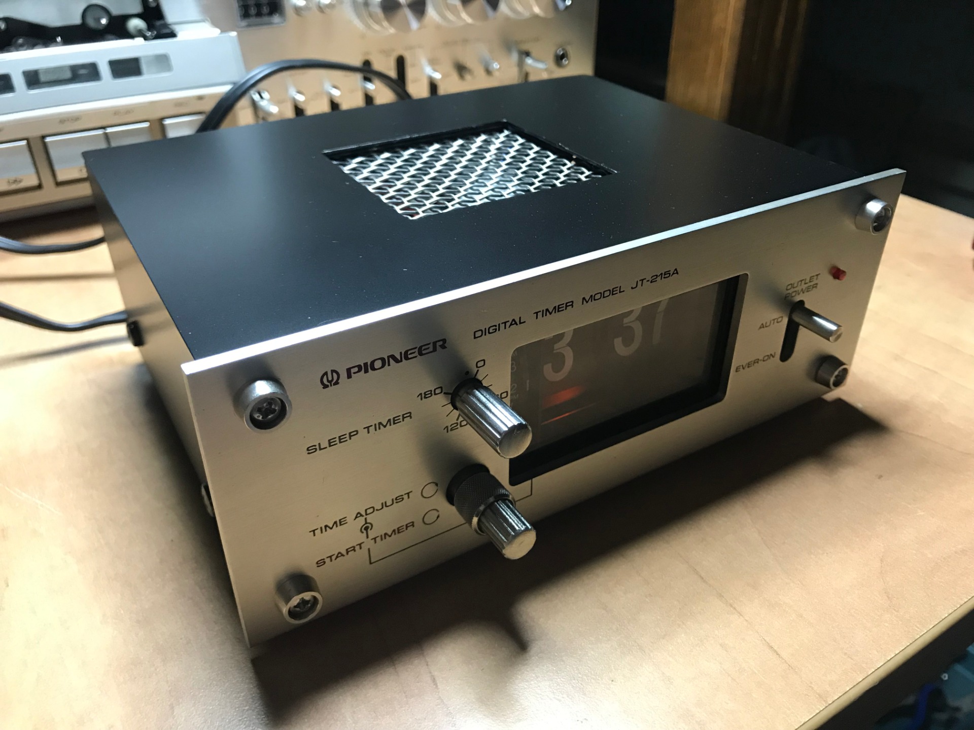


See the end result here!

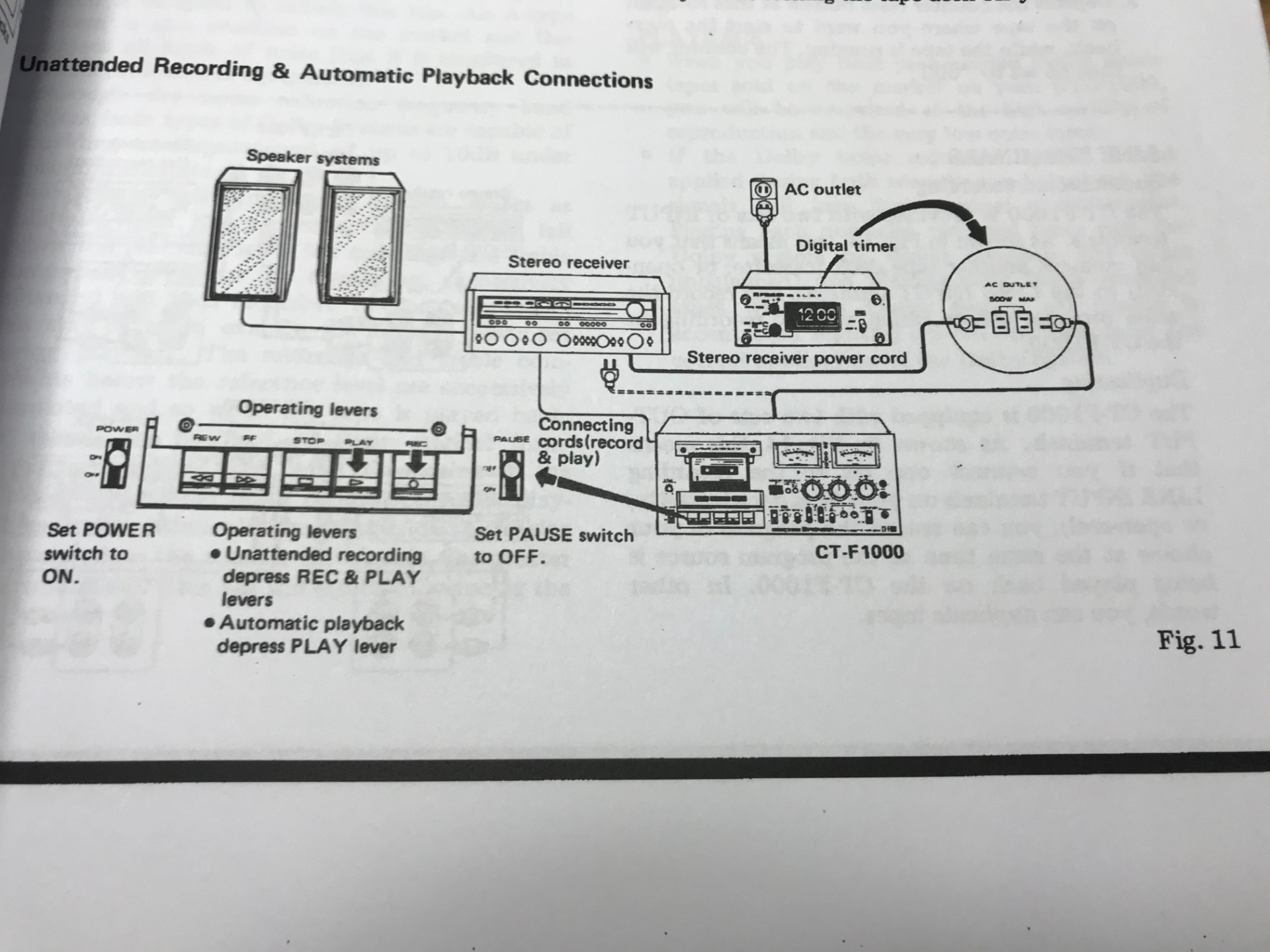
Even better if you put these two side by side. This timer is used as an example in the manual of the CT-F1000 Cassette deck. It fits seamlessly with the device, they were also built around the same period.

For now I will have to see if it continues to run well. But have some confidence in it. It was a fun challenge and I'm happy with the result!
October 20, 2019
Related pages:
- none :-/