
3M Cantata 700 Player
The Cantata 700 BMS is a background music player (BMS stands for Background Music Player).
It's a mighty device, uses mighty large cassettes. And works without any external connection (except for the voltage source). It works, but far from optimal, so it is completely dismantled for inspection and much-needed maintenance. Watch and read how I write the report while I repair the device at the same time!
March 3, 2022

Just a quick word in advance, the player is a specialist in the field of audio equipment. The device is specifically designed to bring music to factory halls or shops. Although the device itself is so far unknown, there is a chance that you have ever heard music from this device. The last sentence is quite literal because:

The device has been in use in the Netherlands for years!
It was quite a surprise for me to see that this American device was used in the Netherlands while I had it imported from Spain. Where exactly the device was used remains unknown to me.
At the bottom of the sticker are the details of the office from which this player was rented. The phone number is dated and no longer works.
(I tried calling this with a friend as a joke).

Let's take a quick look at the device before we get started. Here is a view of the top. The large metal plate is where the cassette rests when it is played.

At the top right is a switch with some numbers. This is the timer. You can let the device play continuously. Or with a break every 30 minutes. So 24-6 is playing for 24 minutes, with a 6-minute break, so 15-15 is half-half.
The original switch is missing, but it can still be operated. I have not yet tested the functionality.

The rest of the controls are first. At the top is a light that shows whether the device is on or off.
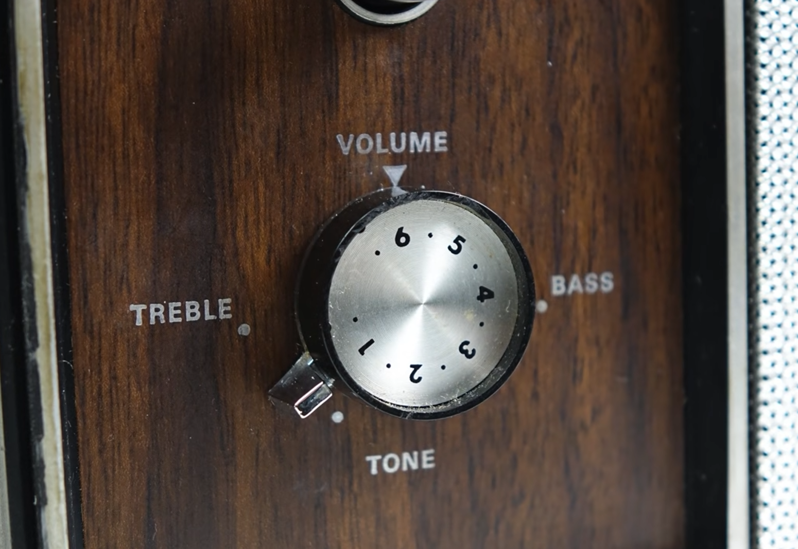
Below it are the on and off buttons followed by the tone and volume buttons.
The button with the red dot is the volume knob. Below it is a lever with which you can adjust the tone, but this control does not work properly. The further he is at Treble, the more noise and halfway between treble and bass the bass spontaneously appears, but immediately very bright. So something I have yet to look into.

A photo of the reading area should not be missed. Two pinch rollers and a single playback head. The operation resembles an 8-track player. The head switches up and down between two positions. This happens automatically when the cassette has reached the end. After this, reverse the playback direction and the head reads the other half of the tape.
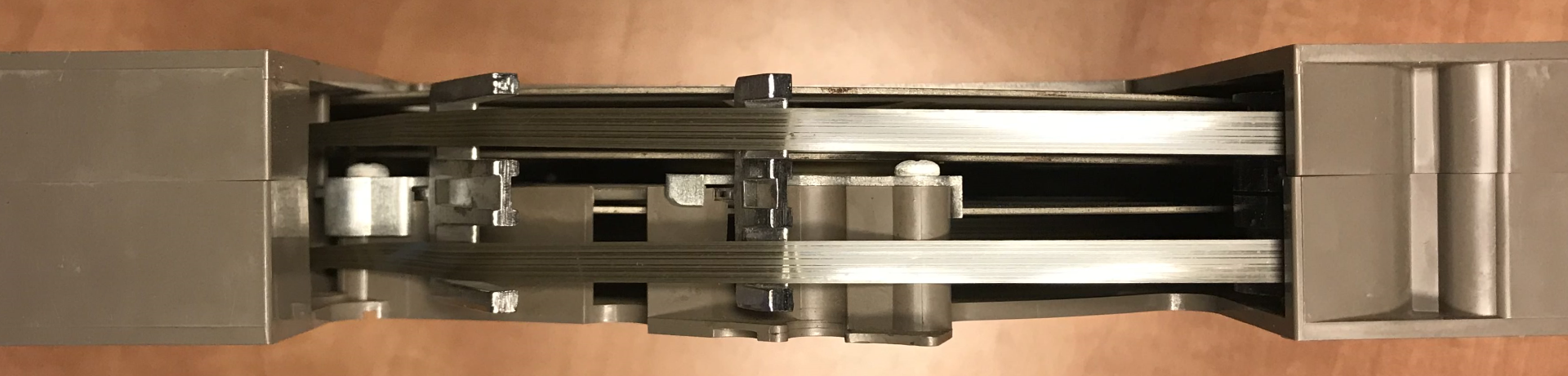
Here's another photo of a cassette where the head and pinch roller come into contact with the tape. As you can see, two pieces of tape are visible, because on the left is a roll where the tape is reversed and comes back. The head only needs to change height to get to the other track of the tape.
Striking about the head is that it is a Mono head, but what strikes me the most is the heavy wear on the head. There are probably hundreds if not thousands of hours of music played on this unit when the head is worn out that far! I may have to look for a worthy replacement in time.

Furthermore, a view of the rear. A fixed cord and a data plate. Here is the real name of the device '94ZB'. There are still connections for speakers and a microphone on the right. I tested both connections, but there was no sound from the connected speaker and the microphone could not be heard either.
It is also a 230VAC model (or with variable power supply). Which is quite rare given that these originate from America where 120VAC is dominant. This also means that the player is set to a mains frequency of 50Hz. According to the type plate, the device should be able to handle both frequencies.
Let's take a look at the device. The switches work, all parts turn and it also plays music.
Nevertheless, you can hear that the reels in the cassette make a scraping sound. This is due to the central axis of the machine, which is slightly bent, so that the coils are also angled. As a result, the spools touch the cassette itself and start to scrape. This also causes the playback speed to be unstable.
In this movie, the scraping and the bent axis are emphasized again during the testing of one of the cassettes. The repair of the cassettes themselves can be read on this page .
There are also a number of other defects including:
- The on and off buttons do not work optimally.
- Wires in cord are visible.
- The speaker sometimes crackles (may be due to external source).
- Unwanted noises come from the machine during normal use.
- Parts on the housing are broken, they rattle through the machine.
- All moving parts must be checked and lubricated.
- The volume knob is not yet seated properly.
- The timer button is missing.
- The grille at the front is slightly dented, can this still be dented?
- Completely refurbishing the appearance?
And there are bound to be some problems...
Enough talk about the operation of the device and its defects, time to do something about it!
A lot of tools and resources are again discussed. An overview can be found below.
Tools:
- Screwdriver Phillips (PH2)
- Grease (preferably ball bearing grease)
- 96% alcohol (Ketonatus)
- Cotton swabs
- Different locking pliers
- Tweezers (for hard-to-reach places)
- Soldering iron, tin and de-soldering material
- Passive electrical parts (capacitors)
- Multimeter
- Way to keep screws/parts separate (a sheet of paper and tape)
- Modeling paint (silver) (optional)
- Compressed air
- Super glue (for broken parts)

I have to admit that I've messed around with the device before, but haven't opened it yet. I still have 2 screws here, a black piece of plastic (part of which is still floating around in the machine) and the old button, the button you see here is not the original, the button that is on it now is not either...


Because the machine was missing the original button, the previous owner had been kind enough to put a new one on it himself. This works but does not clamp well on the shaft so that it comes loose easily. I eventually replaced it with a metal knob. One that should be the right size.

I took a shape in mind, measured it and wrote it down. It's time for new buttons!
Now that the button has been replaced, the device can be disassembled for major maintenance.

The cover is secured at the back with four screws. I remove it with the lid off so that I can work on the device more easily. The lid will probably get in the way.
The plastic panel on the right side is secured with plastic plugs. If you carefully pull the panel up, the plugs give in and the whole comes loose without much effort. Make sure that the plugs do not break. The plastic has probably become very stiff after all these years.
The front panel is screwed on with two plastic feet. When you unscrew this, the panel is only clamped at the front with two feet. Pull it off by pulling the panel back.

Part of the mechanism is hidden under the panel. This piece controls the position of the head and pinch rollers.

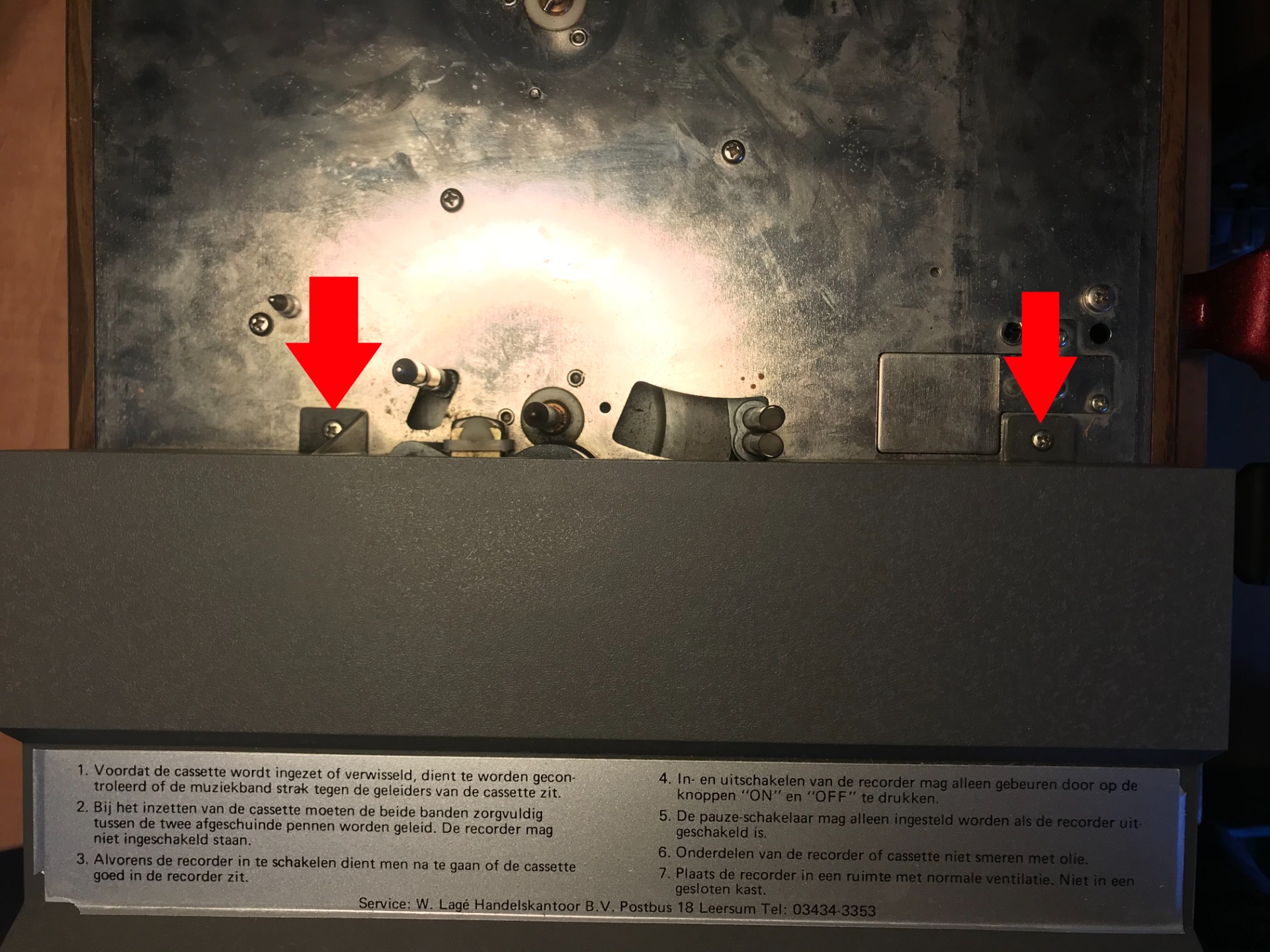
To get to the underlying piece, some screws have to be loosened, which I have indicated with red arrows.

After this, I turn the device over and remove these two screws.

The metal part of the machine can now be slid back, but there is still a small thing left before it can be taken out completely.

The speaker is still connected, the plugs can be disconnected without much effort. They are labeled as 10 and 11 in my case.

After this, you slide the superstructure out of the housing via the rear. Note that the wooden housing is not very strong and the superstructure has to slide out completely if it is to be free from the rest.


I forgot that the tone button also had to be released, but it releases automatically when you slide the superstructure out. Incidentally, the other broken parts are still rolled out of the machine.

The broken parts were once stuck here, and must connect the plastic front to the superstructure of the machine. I'll have to see if this can still be done.


Just a quick look now that the superstructure is out. The electronics are located at the bottom and the mechanical part is located between the metal plating. The mechanical part is what we're going to focus on first. I could now access some parts, but I don't want to do half the job, the top metal plate will have to be removed for this, which turns out to be a nice job.

The superstructure sits like a waffle together with bushes, to separate the top plate all screws that are fixed in these bushings will have to be loosened.

Almost all screws in the top plate must be loosened. I number them with a marker and end up with 11 screws. The marker is also easy to wipe off afterwards, so easy in fact that I have to be careful not to do this by accident!

I stick the screws on a blank A4 paper and write the numbers on it.


The mechanism that operates the head and pinch rollers is also connected to the assembly below. Instead of screws, these are secured with circlips. I mark them with lines and carefully remove them.

Afterwards, it turns out that marking is not necessary here. the clips are the same size.


With the circlips out, these two springs can also be released, they keep the pinch rollers in a certain position as

You can now lift the pinch rollers off the shaft together with the metal bracket to which they are attached, make sure that between the two are a number of plastic rings that also come with it.

The two are very similar but you can distinguish them from each other because they are mirror images of each other.


With the pinch rollers off, the head can come off. First I lift off this metal bracket, it keeps the head pressed down. After this you can lift the head with its metal part. Pay attention to the wiring!


Now that the head is gone, the 'program wheel' can also be lifted off at an angle.


The status light also needs to come off, although I first wanted to remove the ring behind it, the spring came loose instead. However it turns out, the lamp is now off. Now only the lead-through of the cables that are clamped in the metal part, you can loosen these with a twisting and pulling movement.


Finally, the small pin that is secured by the central shaft must also be released. you can wriggle it out with a small locking pliers. I stick it with the rest on the A4 paper


To be honest, I hadn't really noticed this one before, perhaps because I've seen the same type of text so many times on different devices...
Luckily I don't have to take the back off, so I stick to the guidelines from the manufacturer ;-).


Although the top is now physically loose, you still have to be careful with the decrease. Several parts still stick through the plate: The brake. the timer, the central shaft and finally the capstan.
Especially the 'pressure shaft' will work against you, it has notches in the shaft that will jam, because the shaft is under tension with a spring. you will have to guide this axle for a while when you take it off.

Carefully and with some effort I lift the top off.

Finally I get a view of the inside of the machine. Here you see countless moving parts. Some parts such as the capstan and thereby the flywheel (the large metal wheel) are loose now that the top is gone.


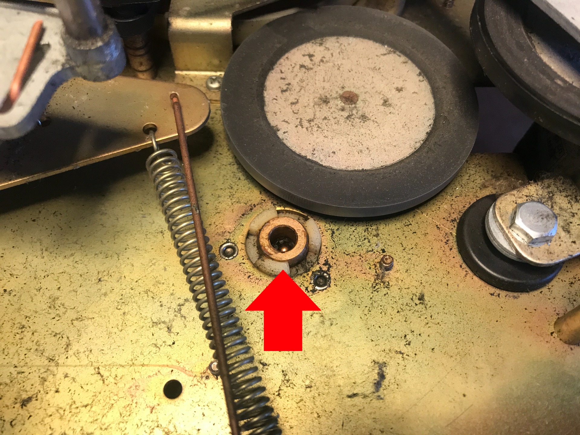
There is also an axis loose in the device. Normally this is mounted in the hole in the second photo, but now that the top is off, nothing can hold the axle upright. In normal operation, the shaft holds the previously mentioned program wheel so that it cannot move freely.

You can lift the flywheel out of the device at an angle, at the same time push the rubber wheel to the right of it to the side to make it easier to remove. The flywheel rests in a notch which I also have to clean because it is full of dirt and grit.
Now that I can reach all parts well and there are no more loose objects swinging through the machine, it is time for a major cleaning. The device has accumulated quite a bit of dirt over the years. I have already removed some of the dust heaps, but a lot of fluff and grit still roam through the machine. Even a little spider once had a cozy time there.

Before cleaning, I take the device outside to blow it with compressed air as far as possible.
And what a difference that makes! Somewhat sarcastic as it's still a mess. I managed to blow out the loose dust, but I will still have to manually brush the rest. The reason that so much dirt remains is because there is a thin layer of oil scattered in the machine. How this came about is unclear to me because I read somewhere that you should certainly not lubricate the machine with oil, chances are that the previous owner has attempted this. The cause is not so important to me, as long as I can get it clean again.

I swear by this stuff these days, 96% alcohol aka 'Ketonatus'. You can get this remedy for a few dollars at your local drugstore. I won't mention the name of the chain and I managed to hide the 'good' label...


I had the fantastic idea to get makeup pads, dip them in alcohol and wipe them along the parts. The result speaks for itself, the pads absorb a lot of dirt, but due to the rough finish of the device, the pads leave behind a new layer of white down. So I have to look at other options.
Simple tissues dipped in the same liquid make more difference, but only in the places I can reach because the tissues also tear quickly and I can't get them into the small cracks and corners that I hoped to reach with the pads. So I'm dependent on the method that I know gives real results...

With cotton swabs I get into the corners much better than with the previous methods. The only problem is that I can only clean a small area before I have to replace the swab.

Although I can't reach everything, there are parts that I can now clean well. Yet I notice that I have lost a lot of time and cotton swabs with this cleaning, after fifteen minutes of brushing and scrubbing I decide to only walk the important parts. It's just too much work to get everything clean. The layer of oil that is on everything does not make it any easier either.
The fan that is on the motor is one of the important parts that I will go over. The difference speaks for itself. Although it would be easier to clean this one if I take it off for a while, I decide to leave it in. The fan is very fragile and the blades break quickly if you treat it too roughly.

The next part I'm going to tackle is the circuit board. The way in which the copper traces are laid tells me that it is a fairly old printed circuit board. Probably 60's or 70's. There is a good chance that the printed circuit board is still soldered by hand.
The circuit board is attached to a bracket, although I can't get the circuit board off the bracket quickly, I can easily remove the bracket from the rest. There are 6 screws holding it all together. two on the underside of the machine and four on the back around the connections. Pay attention, because if you have loosened the screws at the back, the back will come apart from the rest and everything is only attached with wires.

The wires to the printed circuit board are not very long, so you do not get much freedom of movement, what you can still do is unfold the various brackets in which some wires are clamped, here as an example the gray wire to the display head.

The printed circuit board is quite simple, no microchips or other fuss, simple resistors, transformers and last but not least (electrolytic) capacitors (also called 'elco'). And we haven't decided on the latter for the time being!

If there is one thing on a printed circuit board that should be replaced after so many years, it is the capacitors. These lose strength over the years, and if they don't you still have a chance that they will leak and empty with all its consequences, the latter is what you want to prevent.
Oops, too late! Two have already died! Fortunately, the damage was limited, the substances that leaked from the capacitors did not get very far. I will therefore have to replace these two, of course I decide to take the rest with me immediately.
It is striking that the device still seems to work quite well despite this problem. The speaker sometimes crackles (which could be a reason) and the microphone and external speaker connections didn't produce any sound at all, the cause is probably here. This also means that the difficulty of this repair goes up significantly. You will need to have quite a bit of technical knowledge to properly tackle this problem.
In order to tackle this problem properly, I have to read the labeling on the capacitors, because they state their capacity (in farads) and the voltage (voltage) at which they work. I hereby make a drawing and list and then order them. The only annoying thing about these models is the mounting method. Modern electrolytic capacitors stand vertically (radially) on the printed circuit board like a turret, the old ones are still mounted horizontally (axially). In addition, I need to be able to separate the circuit board from the machine itself if I want to have good access to everything, which probably also means that the wires on the circuit board have to be disconnected...

I made a quick sketch of the locations and captions in MS Paint. The ones around the green frame are on the printed circuit board. There is also a separate electrolytic capacitor on the housing itself (yellow frame), but this is almost negligible. The separate electrolytic capacitor is a so-called 'suppression capacitor', which can be confirmed by the low values it has.
The past few hours I have been busy ordering the relevant capacitors, only a single website can offer me all of them, except for the suppression capacitor, the latter cannot be found on any web shop and again, with its low values, it is negligible. The order has been placed and it is expected to arrive on March 17th, so I will have to wait for this. Since this page is now also starting to get a nice length, I will continue this on a second page.
14 maart 2022